Marking Arbitrary Intersections
This tutorial is intended to give you the skills necessary to:
Understand the geometric constructs underlying a shape
Be able to utilize these constructs to identify intersection points within a DrawScript program
See the Introduction to DrawScript tutorial for more information about DrawScript.
DrawScript template with the mark-intersections rule.Tutorial 6.3dm.Part 1: Carriers and Shape Signature
Within a shape, the geometry that you can see (points, lines, arcs, and the like) are all called elements. In general, an element is defined by its boundary and its carrier.
In the Shape Grammars paradigm, the boundary of an \(n\)-dimensional element is a shape composed of \((n-1)\)-dimensional elements that separate the “interior” and “exterior” of the \(n\)-dimensional element.
Note
Points are \(0\)-dimensional; lines, arcs, and arbitrary curves are \(1\)-dimensional; planes and surfaces are \(2\)-dimensional; and solids are \(3\)-dimensional.
Technically, closed curves (like circles) and points have no boundary.
Note
The formalism defines a boundary operation on shapes, not on elements. So to find the boundary of a single element, you would actually find the boundary of the shape composed of that single element.
The carrier of an \(n\)-dimensional element is something more nebulous. It is the “infinite extension” of the element, the geometry that you get if you remove the element’s boundary. For a line, this looks like the infinite line our line element lies on. For an arc, this looks like the circle the arc is a segment of. Traditionally, carriers are represented by an equation, and elements can be considered to have the same carrier if they have the same underlying equation. Carriers define important properties of an element: it’s dimensionality, curvature, position in space, etc.
Carriers each define their own algebra: defining join, meet, difference, and partial order operations. These carrier algebras combine to create the algebra of shape that defines the same operations on entire shapes with multiple carriers.
Shape Signature
In Shape Machine, shapes are given a signature that aids in the embedding process. The signature of a shape is built upon the intersections of carriers, which are each labeled by a registration point. The main idea is that if a shape \(u\) is a subshape of \(v\), then the signature of \(u\) can be found somewhere within the signature of \(v\).
During embedding, registration points in the query’s signature are matched to registration points in the design’s signature. Once a potential match is found for each query registration point, the entire shapes are tested for the subshape property. By matching the signatures first, fewer comparisons are needed.
Theoretical Computer Science Details
This matching problem resembles subgraph isomorphism, which is NP-Complete (meaning it cannot be generically solved in a reasonable amount of time). Even worse, shape signatures are actually hypergraphs, as each carrier can induce multiple registration points (carriers become the hyperedges of the hypergraph).
In the case of shape embedding, however, the problem is easier to solve than the general case. Because registration points have restricted spatial relationships, only a handful of registration points need to be matched to determine a transformation. If the transformation is valid, all other registration points in \(u\) will be transformed to a valid match in \(v\).
Part 2: Marking Carrier Intersections
With some definitions out of the way, we can talk about how Shape Machine can be used to place points at intersections within a design. Specifically, Shape Machine can place points at intersections of carriers within a design. Each of these intersections is a registration point.
This behavior can be confusing at first, but it is quite powerful with a careful setup.
Marking Intersections in Rule Sequences
A new type of rule is introduced to rule sequences (and DrawScript) that tells Shape Machine to mark intersections of carriers:
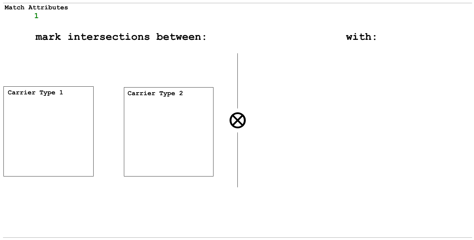
The left-hand side a mark-intersection rule has two boxes, and the right-hand side is empty. Within both of the boxes of the LHS, you can place a single shape element. These elements tell Shape Machine which types of intersections to mark. For example, if in one box you place a red line and in the other you place a green arc, Shape Machine will mark intersections of all red line carriers and all green arc carriers. The type of point Shape Machine will use to mark the intersections is identified by placing a single point in the RHS. For example, placing an orange point on the RHS of the rule will mark all found intersections with an orange point.
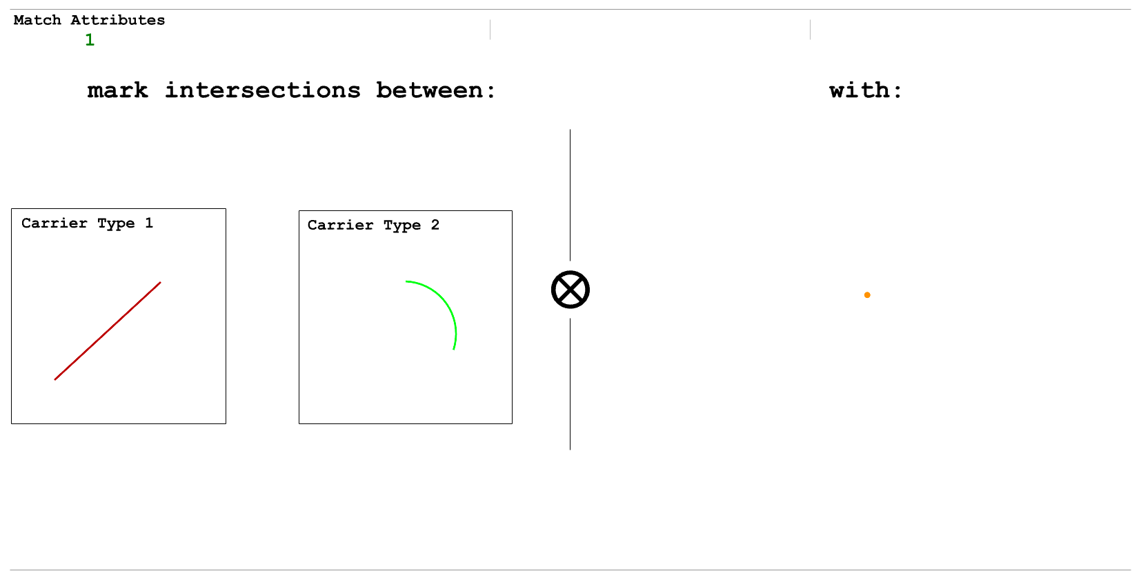
Example mark-intersection rule, as described above. Note that a circle does not need to be provided to indicate marking intersections on arc carriers.
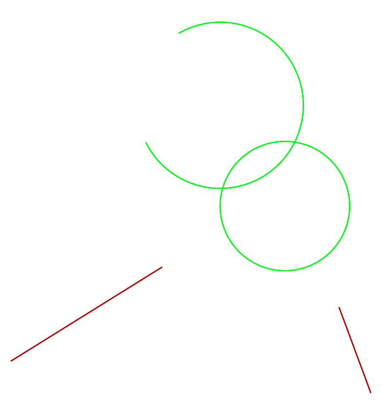
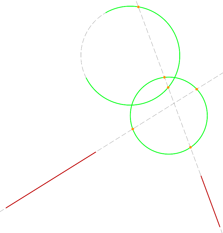
Above left: Initial shape to apply the example mark-intersection rule to.
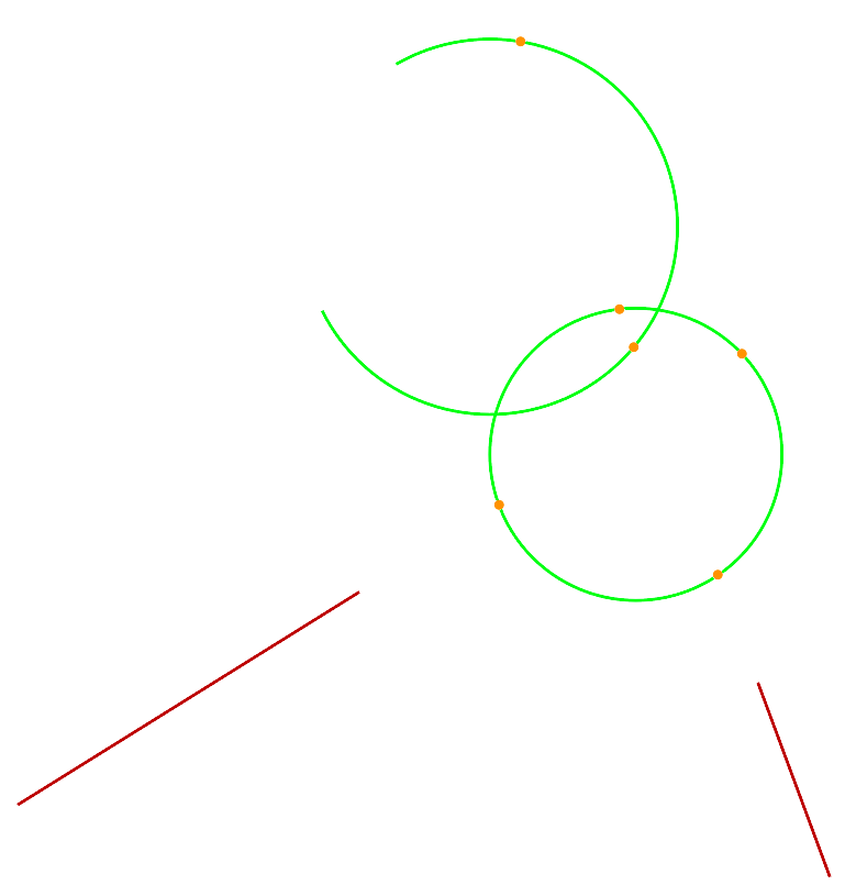
Above right: Result after applying the mark-intersection rule.
Right: Result with carriers shown in dashed grey lines. Note how the intersections
of carriers are marked, not intersections of elements.
If you don’t want Shape Machine to restrict the intersection marking to specific
attributes, you can set the Match Attributes parameter to 0. This will tell
Shape Machine to mark intersections based solely on carrier type. Two lines means Shape
Machine will mark intersections between every pair of line carriers; an arc and a line:
all arc-line carrier intersections; and two arcs: all arc-arc carrier intersections.
If you do this, you are likely to create many more points than you want.
Important
Shape Machine will mark all intersections that it finds between carriers indicated by the mark-intersection rule. If you’re not careful, many of these points may not be useful to you. As such, it is usually a good idea to curate the geometry in your design such that the carriers Shape Machine looks for are uncommon within your design. Using unique layers to isolate the carriers you want to find intersections of can be very helpful.
Note
Shape Machine can only find intersections of two types of carriers. If you would like to find intersections of three types, you can run the rule twice with different output points, followed by rules that look for the two different types of points you instructed Shape Machine to create.
Part 3: Exercises
Exercise 1: Carrier Intersections in Nested Squares
In this exercise, we’ll use the nested squares to demonstrate how Shape Machine marks intersections of carriers, not just visible geometry.
Step-by-Step Guide
Create the Nested Squares
Using similarity, look for a black square, replace it with a green square and an inscribed black square. Loop this twice so that there will be 3 squares in the final design.
Recolor every green line to be black.
Mark Intersections of Black Line Carriers
Using the new mark-intersection rule, place a black line in both of the squares on the LHS. This tells Shape Machine to mark all intersections of black line carriers.
Place a blue point on the RHS to instruct Shape Machine to mark these intersections with a blue point.
Key Points
Marking carrier intersections can create a lot more points than you might expect.
Being able to mark intersections of line carriers can make it possible to place points at these intersections, even when the line carriers meet at an arbitrary angle.
Exercise 2: Computing Square-Roots
This exercise is based on the construction provided in this Math StackExchange answer.
Initial Shape
Your initial shape should be a single horizontal black line with the left endpoint marked blue and the right endpoint marked orange. This provides an orientation for Shape Machine.
The length of the line is what the radicand will be. By the end, Shape Machine will shorten this line such that the new length is the square root of the original length.
Create a Length-One Line to the Left
Using isometry, look for the blue point. From this point, create a line of length 1 extending to the left. Mark the other end of the new line with a pink point.
Keep the blue point on the RHS of the rule so it isn’t deleted!
This is an indeterminate query, but we can leave
Angleat0, which forces the line to be placed to the left of the blue point.To create a line of length 1, run
Line, place the first endpoint and, before clicking to create the second, type 1 to set the length. This line will look fairly short in the rule because the file is in millimeters.
Create a Red Circle with Diameter of the Line from the Pink to Orange Points
Using similarity, look for a black line with one end at the pink point and one end at the orange point. Replace it with a red circle using that line as its diameter, deleting the original line and the two points.
After running this rule, the only remaining geometry should be the new circle and the blue point that was the left side of the original black line.
Create an Upwards Red Line from the Blue Point
Using direct isometry, look for the blue point. From this point, create a red line extending upwards. The length of this line doesn’t matter, as long as it is vertical.
Keep the blue point on the RHS of the rule so it isn’t deleted!
Direct isometry is necessary to ensure that the line is placed upwards, not downwards. In an angle-indeterminate query, the RHS can be reflected across the angle specified in the
Angleparameter. Because this is0, the RHS of this rule can be flipped vertically, which would make the line extend downwards. Technically, this is fine because we’re just using it to mark intersections, but it’s a good habit to be in.
Mark the Intersections of Red Line and Arc Carriers with Red Points
With a mark-intersection rule, place a red line in the first box on the left and a red arc in the second. On the RHS of the rule, place a single red point.
This will mark the intersections of the carrier of the red line created in step 4 and the carrier of the red circle created in step 3.
Note that both intersections will get marked here.
Create a 2-Point Circle Through the Marked Red Points
Using similarity, look for two red points. Replace them with a black circle that passes through both (with both points creating a diameter).
The mark-intersection rule creates two points on the red circle, and we can use them to create this new circle.
The radius of this circle is the square root of the length of our original line.
You can create a 2-point circle like this by running
Circleand clicking2Pointin the command prompt or by typingpand pressing enter.
Replace the New Circle with Its Horizontal Radius
Using similarity, look for the black circle created in step 6. Replace it with its radius extending horizontally to the right. Place an orange point on the right side of this new line.
Remove All Red Geometry
You will need 3 rules here. Create one each to remove all red lines, all red circles, and all red points.
After running this program on your initial shape, the output will be a line that looks like the original but has a length that is the square root of the original’s.
Note
Even though one of the points under step 4 talks about using direct isometry to
create the vertical line, the other rules creating lines with angle-indeterminate
queries create horizontal lines. Because a reflection across the Angle parameter
doesn’t change a horizontal line in the RHS, we don’t have to use direct transformations
here. This means that you could do step 4 with regular isometry, output a horizontal
line, but set Angle=90.
Key Points
The mark-intersection rule makes it possible, in general, to find where a line carrier intersects with an arc carrier. This is otherwise not possible unless the line carrier passes through the center of the arc carrier.
Using direct transformations and points/circles on the LHS of a rule with
Angle=xcan let you create lines of a specific length at any angle (xdegrees) you would like. If you don’t use a direct transformation, the output could be reflected across the angle specified.
Part 4: Conclusion
In this tutorial, you learned:
Carriers and Shape Signature: The features of shapes that makes marking intersections possible in Shape Machine.
Mark-Intersection Rules: A new type of rule for rule sequences and DrawScript that instructs Shape Machine to place points at the intersections of all instances of two types of carriers.
Mark-intersection rules make it possible to:
Identify intersections of geometry that is otherwise not supported by Shape Machine.
Bypass workarounds to find intersections of line carriers such as:
Extending lines until they meet at a point that can be identified under affinity
Using incredibly small lines in the LHS of a rule
Glossary
Shape Element: Individual pieces of geometry that make up a shape (lines, arcs, points, etc.)
Element Boundary: A shape that represents a separation between the interior and exterior of a shape element. Closed curves have no boundary. Technically, boundary is only defined for entire shapes in the formalism, not for individual elements.
Element Carrier: The “infinite extent” of an element. Often represented by an equation. Defines an element’s dimensionality, curvature, position, etc.
Shape Signature: A property of a shape that aids in the embedding process. This is a hypergraph with carriers representing hyperedges.
Registration Point: The nodes in a shape signature hypergraph. They are formed by intersections of carriers (and the centers of arc carriers).
Mark-Intersection Rule: A DrawScript rule that instructs Shape Machine to place points at the intersections of two types of carriers, optionally limited to specific element attributes.